
HEX V8 — Preprint (English)
HEX V8: a ternary hexagonal 2D symbol with scalable capacity and mobile readout under controlled printing conditions
Author: Jorge Figueroa
Affiliation: Independent researcher, Satinus E.I.R.L., Chile
Contact: jorgefigueroacifuentes@gmail.com, satinuseirl@gmail.com
Date: 2026-07-12 (EN preprint, narrative cohesion)
Abstract
Dominant two-dimensional symbologies---QR Code, Data Matrix, and Aztec---encode payloads as binary modules on a rectangular grid. That design favors ecosystem support and built-in smartphone readout, but it imposes a practical ceiling on recoverable bytes when the symbol must remain legible under mobile optics, typical stand-off distance, and monochrome printing.
This paper asks a bounded question: under explicit millimeter-scale printing rules and with a dedicated reader, can a monochrome symbol with non-grid geometry and more than two states per physical element carry more useful bytes than a reference QR at comparable legibility? The evaluated answer is HEX V8 (Hexagonal Encoding eXtended): a ternary triangular mesh packed as S2-octal rhombi; an 8-byte self-describing header; Reed--Solomon over GF(256) with native erasures on the $(1,1)$ pair; ring interleave; deterministic padding; and a checkerboard visual layer (spec v1.1), decoded by a ring- and $N$-aware mobile pipeline.
Under a declared protocol (RS-M, 300 DPI at 100%, 25–35 cm capture, tri_mm (mean printed triangle edge, in mm) ≈ 5 mm, Auto session N8→N15), a closed capacity model, a 15/15 synthetic regression, and paper field tests with Android reader 0.4.7 on one documented device yield 137 B useful payload at HEX N15 (printed ≈ 85 mm) versus ~37 B for a ~25 mm reference QR at matched triangle-edge legibility. That is not a same-footprint claim: at fixed $\mathrm{tri_mm}$, raising $N$ enlarges $\mathrm{code_mm}$ (e.g. N10 at 58 mm carries 35 B; N15 at 85 mm carries 137 B). HEX V8 does not replace QR universality or shrink a small-QR footprint; it is a specialized monochrome channel that requires a dedicated application, controlled printing, and strict angular framing at high N.
Keywords: 2D barcode; ternary encoding; hexagonal mesh; Reed–Solomon; mobile computer vision; payload capacity; QR Code; Data Matrix; Aztec Code; monochrome symbology
1. Context: two-dimensional codes and capacity under legibility limits
Two-dimensional barcodes act as a physical channel: they convert a data payload — a byte sequence meaningful to the application — into a printable or displayable pattern, and a camera-equipped reader attempts to recover those bytes. In practice the payload travels in the clear within the symbol; error correction protects against printing and capture damage, it does not substitute for encryption.
The dominant model — QR Code [1,7], Data Matrix [2], Aztec [3] — packs information into binary modules (two states per cell: light or dark) on a rectangular grid. After detecting synchronization markers (finders, bullseye, perimeter), the reader samples each module and reconstructs bits; the logical layer applies Reed–Solomon [5] over GF(256) on blocks of bytes. The version or the module size scales capacity: a higher version means more rows of modules and more possible bytes, at the cost of a physically larger symbol or smaller cells that are harder to read.
That design prioritizes ecosystem: standardization (e.g., ISO/IEC 18004 [1]), readers built into smartphones, and well-known printing workflows. The structural cost is a useful-capacity ceiling under mobile legibility: how many recoverable bytes remain available once the minimum printed element must stay readable with mobile optics, a typical distance of ~25–35 cm, and everyday monochrome printing [6,17]. Shrinking the module raises nominal bits/mm² but reduces margin against blur, substrate curvature, and effective camera resolution—so “higher density” and “more useful payload under field reading” are not the same objective.
Other symbologies address the same problem with different trade-offs. DotCode [16] targets high-speed industrial printing and remains binary per dot. Multichannel color codes [13,14] multiply states per cell, but require faithful color reproduction and camera calibration — more fragile conditions than monochrome in the field. MaxiCode [15] uses hexagonal cells within a closed messaging format, not an open codec for arbitrary bytes. Taken together, the most widespread ISO family shares one assumption: one module ≈ one bit, sampling over a grid (or rectangular equivalent), and reading pipelines designed around that assumption [8–10,17].
Reading with a mobile camera is well documented: detection, perspective correction (homography), binarization, and RS decoding. Those techniques do not automatically carry over to a symbol with a different geometry or more than two states per element without redesigning detection, sampling, and the logical layer. As a design question, it remains open to explore monochrome formats, with a dedicated reader and explicit printing rules, when the goal is to prioritize payload capacity over universality of reading.
2. Research question
Given the landscape of §1, this work starts from an open, bounded question:
Is it possible to design a monochrome 2D symbol, with a geometry different from the binary grid and more than two states per physical element, that carries more useful payload bytes than reference codes (e.g., QR) at comparable mobile legibility, while remaining readable with a dedicated reader under explicit printing conditions?
This does not ask whether we are seeking a substitute for QR in ecosystem, ISO standard, or confidentiality terms. It does not ask whether HEX packs more bits into a smaller printed box than a compact QR. It asks whether there exists a measurable alternative in useful payload when the symbol is printed and read under declared rules: size in millimeters, print resolution, capture distance, and the legibility threshold of the minimum element (tri_mm) — quantified in §4 and §6. Under those rules, raising $N$ trades a larger footprint for more bytes while holding triangle-edge legibility roughly fixed.
The rest of the article recounts how that alternative was sought: what was tried, which layers were added until convergence on the evaluated version, what data were obtained, and what is delivered as evidence. The name HEX (Hexagonal Encoding eXtended) and the V8 protocol designate that convergence; the acronym is unpacked again in §3.7.
Organization. Sec.~3 traces the design evolution through HEX V8 (logical layer in Sec.~3.5; Table 1). Sec.~4 quantifies capacity and print scale (Table 2). Sec.~5 describes the dedicated mobile reader (profiles, stages, and $N$ resolution; Table 7). Sec.~6 states the evaluation protocol (Table 6), reports synthetic and field evidence, and gives a bounded QR comparison (Tables 4–5b). Numbered contributions appear in Sec.~8.2, after the evidence. Sec.~7–Sec.~9 cover limitations, conclusions, and material availability. Appendices index terms and floats.
3. Building the format: design evolution
Starting from the question in §2, a design line opened that would later be called HEX. The format was not defined all at once: this section follows the order in which ideas were tried and layers were added, each in response to the limits of the previous one, up to the V8 version evaluated in §6.
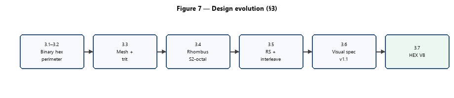
Figure 7. Sequence of design decisions (§3.1–3.7).
3.1 Starting point: binary hexagonal honeycomb
The first concrete proposal was deliberately modest: a symbol with a hexagonal silhouette made of binary hexagonal modules (black/white), inspired by honeycomb tessellation but retaining the bit-per-cell approach of QR. The payload was concentrated on an edge encoded with Reed–Solomon; the interior served mostly a structural function. It was a theoretical testbed: to verify whether the hexagonal geometry deserved exploration before investing in a richer alphabet.
In parallel, constraints aligned with §2 were fixed: no RGB channel [13,14]; no assumption of the phone's built-in QR reader; acceptance of a dedicated reader and explicit printing rules (DPI, size in mm) in exchange for seeking more useful bytes at a declared triangle-edge threshold, not a smaller footprint than compact QR.
3.2 First line: binary edge (insufficient)
The implementation grouped triangles into first-level hexagonal modules and encoded data around the perimeter. Measured capacities came out on the order of 18 B (N8) to 64 B (N20) — far below a comparable QR (e.g., version 10 level M ≈ 652 B under the usual reference).
The thick hexagon as a unit and a perimeter binary channel wasted the interior area and did not compete in density with the mature QR grid. It was necessary to change the alphabet and the packing, not just the outer silhouette.
3.3 Triangular mesh and trit
The silhouette was fragmented into a triangular hexagonal mesh — a barycentric tessellation of alternating upright and inverted equilateral triangles. Each encodable triangle carries a trit, a ternary digit $\in{0,1,2}$. Nominally each trit contributes $\log_2 3\approx 1.58$ bit of information per cell, versus 1 bit for the QR module.
Isolated trits, however, do not form stable bytes nor withstand capture noise without an additional logical layer.
3.4 Rhombus, S2-octal and the N parameter
Trits are packed into rhombi: each rhombus joins an upright triangle with an adjacent inverted one (shared edge). Two trits admit nine combinations; eight map to a 3-bit S2-octal data symbol and the pair (1, 1) is reserved as a native erasure (§3.5.1)—that is the bridge from ternary cells to an octal coding alphabet, not a claim that one trit equals three bits.
The integer N is the number of radial divisions of the triangular honeycomb mesh (how finely the hexagon is subdivided into concentric triangle rings). It is not a QR-style “version number” painted as nested hexagon modules. Higher $N$ adds more encodable triangles and thus more payload rhombi (§4); at fixed $\mathrm{tri_mm}$, it also increases the printed flat-to-flat width $\mathrm{code_mm}$. The atomic unit of encoding is the rhombus, not the isolated triangle nor the thick hexagon of §3.2.
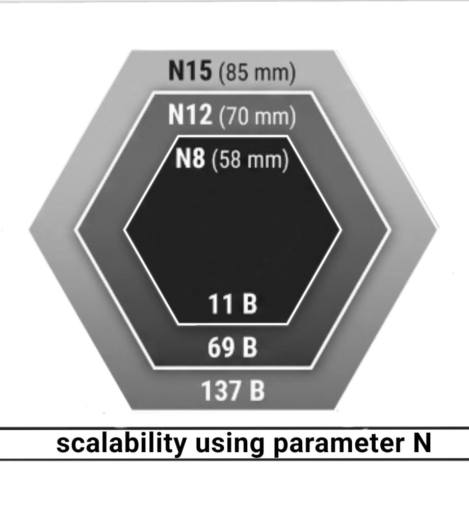
Figure 4d. Printed footprint and useful payload (RS-M) scaling with parameter $N$ (N8 / N12 / N15 subset; Table 2 values). At comparable triangle-edge legibility, raising $N$ enlarges $\mathrm{code_mm}$ and capacity.
Among the alternatives explored in this line —isolated trit, thick binary hexagon (§3.2), and an experimental three-rhombus cell packing— S2-octal offers the best balance so far between capacity, byte/RS alignment and optical trackability (§3.5.1, §7). Grouping three rhombi per hexagon was evaluated only as a packing hypothesis and is not part of the V8 codec; it is mentioned here for design completeness.
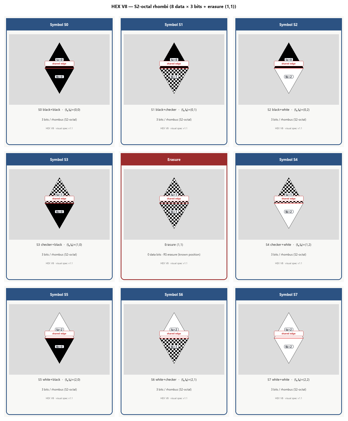
Figure 4b. Rhombus atlas: eight data symbols (3 bits) and the (1,1) pair reserved as erasure. Shared edge between upright and inverted.
3.5 Logical layer: S2-octal, header, interleave and Reed–Solomon
Capture does not return perfect trits: smudges, JPEG compression, blur and classification ambiguity turn the printed symbol into a noisy channel. The V8 logical layer responds with three coupled decisions: a physical alphabet with an erasure signal, a write order resistant to local damage, and a self-contained metadata block.
3.5.1 S2-octal symbols and native erasure
Each rhombus contributes two trits $(t_a, t_b)$. Nine combinations are possible; eight are mapped to data symbols ${0,\ldots,7}$ (3 bits each) and the pair (1, 1) is excluded from the coding table. If the reader classifies a rhombus as (1, 1) — a typical ambiguity of the checkerboard trit under noise — the decoder does not interpret it as data: it records it as an erasure at a known position. In Reed–Solomon, correcting an erasure consumes half the parity of correcting an error at an unknown position; the design aligns the physical alphabet with the most frequent failure mode in mobile capture.
Symbols are packed into bytes (MSB-first, three symbols per byte with one padding bit) before applying RS over GF(256), as in QR, but the unit of visual correction remains the rhombus, not the isolated byte.
3.5.2 V8 Header (8 bytes)
The header is a fixed 8-byte block serialized in big-endian order. It travels at the start of the logical stream and is replicated in the first rhombi of the mesh. Its integrity is protected with CRC-8/MAXIM over the first seven bytes; the decoder rejects corrupted headers before attempting RS (fail-fast).
Table 1. V8 header layout
| Byte(s) | Field | Function |
|---|---|---|
| 0 | protocol_version |
Protocol version (V8 = 0x08) |
| 1 | n_divisions |
Symbol parameter N |
| 2–3 | data_length |
Plaintext payload length (uint16 BE) |
| 4 | rs_nsym |
RS parity symbols of the block |
| 5 | flags |
RS active, rhombus mode, ring interleave, ring pruning |
| 6 | redundancy_factor |
Internal redundancy factor (1 = no repetition) |
| 7 | crc8 |
CRC-8/MAXIM of bytes 0–6 |
The 22 rhombi reserved in §4.1 correspond to $\lceil 64/3 \rceil$ positions needed to pack these 8 bytes as S2-octal symbols in the mesh.
3.5.3 Ring interleave
Without interleaving, a local scratch or smudge would destroy contiguous bytes of the payload. In V8 the encoder orders data rhombi by hexagonal ring of the data mesh (interior → exterior) and, within each ring, distributes them in sectorial round-robin (six honeycomb sectors). This logical write order is distinct from the visual ring of §3.6 (the thick black perimeter used for pose/$N$ detection). Encoded bytes are written in the interleaved order; the decoder reconstructs the logical stream by inverting the permutation (deinterleave).
Practical effect: local damage in the image translates into scattered errors within the RS block, not into a contiguous segment of the message. The header's ring_interleave flag documents that the symbol uses this order; in canonical V8 it is always active.
3.5.4 Reed–Solomon (level M)
All experiments in this article use RS level M (~20% parity over the data block). The encoder computes the block layout (data + parity) within the space available in rhombi after reserving the header and anchors; the resulting rs_nsym value is written into the header so the decoder applies the same configuration without external parameters.
Level M balances capacity against margin for JPEG, mild blur, and trit classification errors — conditions typical of the synthetic corpus (§6.1) and of the paper field tests (§6.2).
3.5.5 Deterministic padding
Rhombi not occupied by header, RS payload, and parity are filled with pseudorandom but reproducible S2-octal symbols. The seed is derived from BLAKE2b-64("HEXV8_PAD" ‖ header ‖ data ‖ N) and an xorshift64* generator produces the trit sequence. Encoder and decoder generate the same padding given the same context, without explicitly storing it in the symbol. After decoding RS, the payload is truncated to the header's data_length; padding is never confused with valid data.
Taken together, the contribution of §3.5 is not Reed–Solomon in the abstract, but the co-design of a native-erasure alphabet + inter-ring ordering + self-contained header + verifiable padding.
3.6 Rendering in ink: visual spec v1.1
Three ternary states must survive monochrome printing without relying on flat gray — ink tends to fuse mid-grays. Implementation convention (aligned with the reference encoder/decoder):
| Trit | Visual representation |
|---|---|
| 0 | Solid black |
| 1 | Checkerboard texture (alternating squares), not gray — visual spec v1.1 |
| 2 | White / light background |
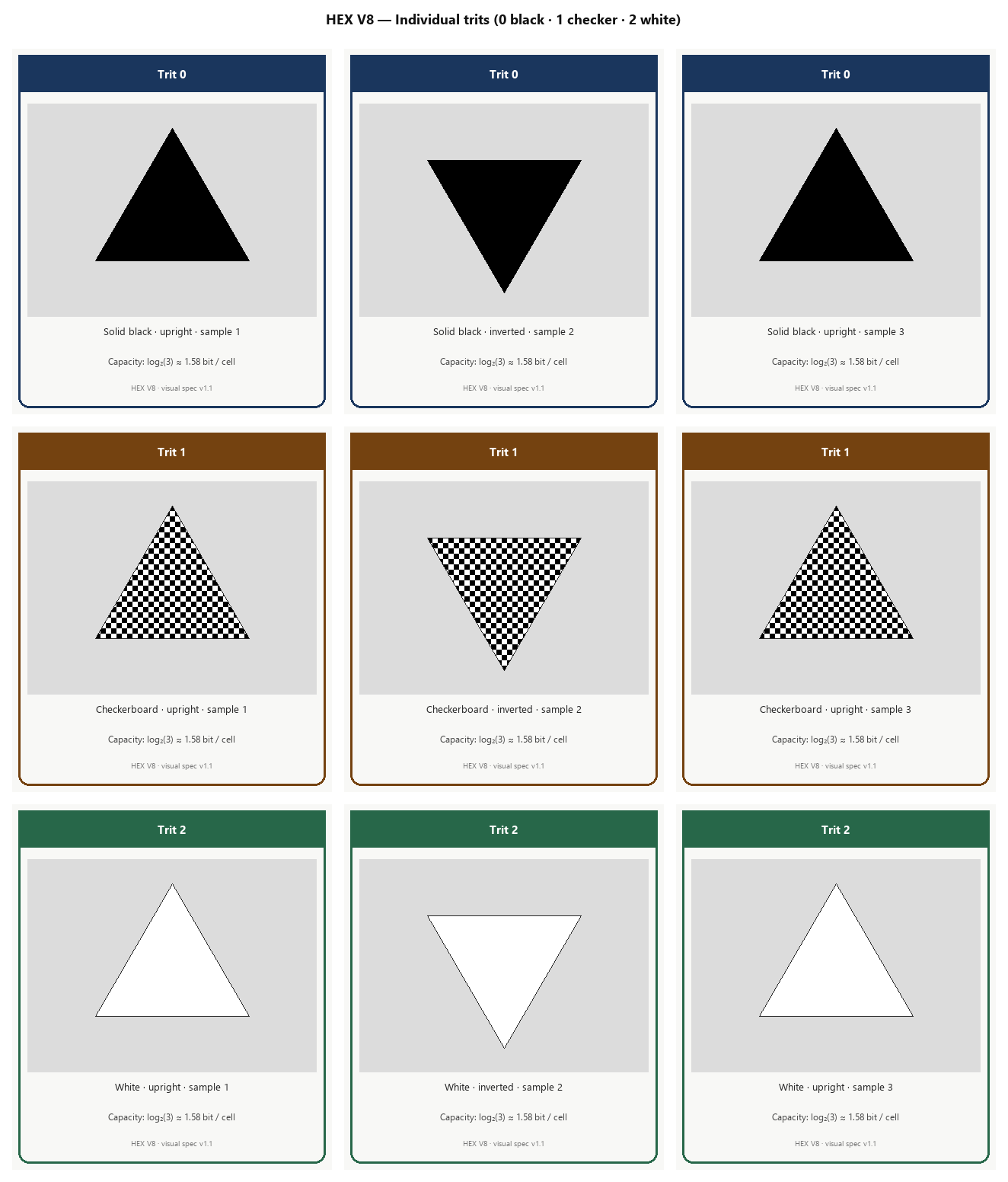
Figure 4. Three ternary states in upright and inverted orientation (didactic atlas). Trit 1 is discriminated by texture, not continuous tone.
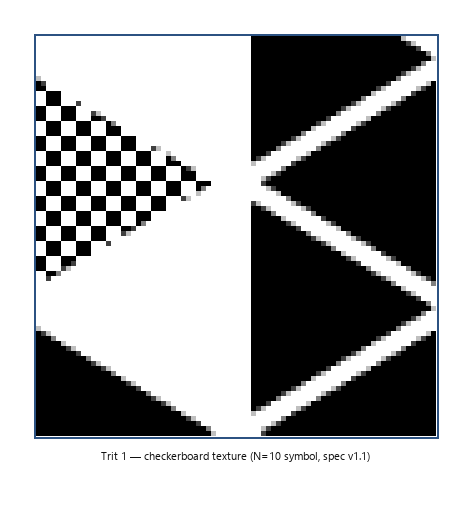
Figure 4c. Crop of a printed symbol: checkerboard under real capture.
A hexagonal visual ring on the perimeter synchronizes orientation and allows estimating N before reading the core. Outside the ring, a quiet zone (white margin) serves the same function as the QR quiet zone. Inside that margin, adjacent to the ring's inner edge, the reference encoder may draw an optional quiet-zone timing pattern: six alternating black/white rectangular segments per hexagonal face. It is a binary calibration band between the ternary data mesh and the visual ring—useful as an auxiliary alignment cue—while pose, scale, and $N$ estimation remain driven by the visual ring and ring ratio (§5.2). Image generation uses 300 DPI, 100% scale, and raster supersampling (details in [18]).
The visual layer is not decoration: trit 1 must be legible by image integral in the camera, not just by human inspection.
3.7 Convergence: HEX V8 protocol
The preceding layers converge on HEX V8 (Hexagonal Encoding eXtended), a bidirectional visual codec: it converts a byte payload and value N into an image (PNG/PDF), and recovers bytes from a photograph.
Encode: header → RS over available space → bytes to S2-octal → ring interleave → padding → triangle map + ring + margin → rasterization.
Decode: grayscale and crop → visual ring → pose and N → homography → trit sampling → rhombi → deinterleave → RS with erasures → header validation → truncation to data_length.
Invariants: within the capacity of §4, roundtrip (decode(encode(data)) = data); given unrecoverable corruption, fail-fast (explicit error, no silent incorrect decoding).
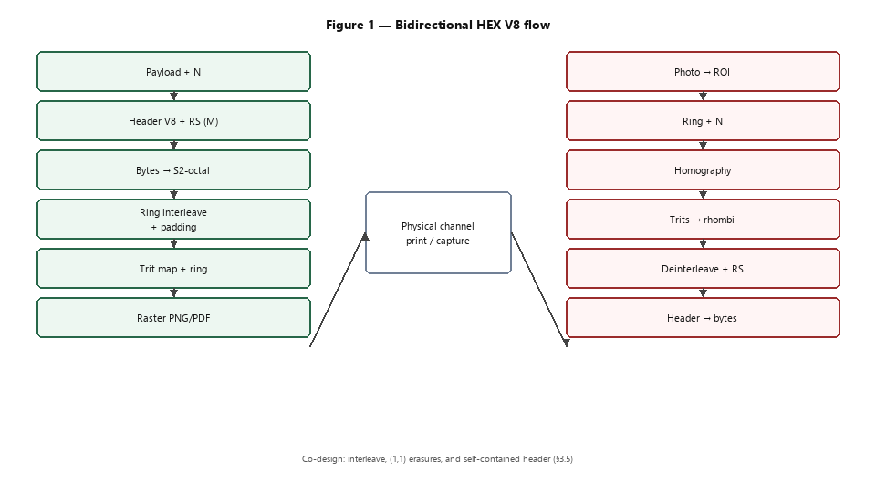
Figure 1. Logical pipeline: encode (left), physical channel (center), and decode (right).
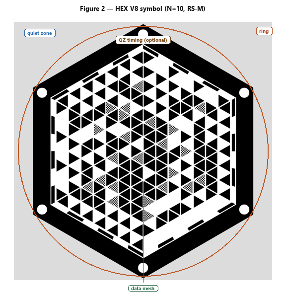
Figure 2. Reference render (N=10, RS-M): visual ring, quiet zone (with optional timing segments on the ring's inner edge), and triangular mesh.
4. Capacity and physical scale
With the format defined (§3), the question in §2 becomes quantitative: how many bytes fit per N, and at what size should it be printed?
4.1 Geometric capacity
Geometry depends on the parameter N (radial divisions of the hexagonal mesh). Two outer rings are reserved for the synchronization visual ring; the interior core is left for data. We define the data kernel:
$$K = N - 3$$
equivalent to $L = N - 2_{\text{visual}} - 1$ encodable rings in the barycentric mesh.
Step 1 — encodable triangles. Per sector (six sectors in the honeycomb), the tessellation contributes $K^2$ data triangles; in total:
$$T_{\text{data}} = 6K^2$$
Step 2 — rhombi. Each rhombus consumes two triangles (adjacent upright + inverted). Data rhombi are grouped into three concentric bands of $K$ positions, with edge overlap between bands:
$$\text{rhombi}_{\text{gross}} = 3K(K-1)$$
Step 3 — fixed overhead (in rhombi, not in bytes):
| Reservation | Rhombi | Reason |
|---|---|---|
| Packed V8 header | 22 | $\lceil 8 \times 8 / 3 \rceil$ S2-octal symbols |
| Timing anchors | 3 | Geometric synchronization (sectors 0, 2, 4) |
| Total | 25 |
Step 4 — geometric bytes. Each payload rhombus contributes 3 bits:
$$\text{pay_rhombi} = 3K(K-1) - 25$$
$$\text{payload_bytes_geom} = \left\lfloor \frac{\text{pay_rhombi} \times 3}{8} \right\rfloor$$
This expression is the geometric capacity: an upper bound on the space available for the logical block (header + RS payload + padding) before accounting for packing efficiency.
Example ($N=15$). $K=12 \Rightarrow \text{rhombi}_{\text{gross}} = 396$; minus 25 $\Rightarrow 371$ payload rhombi $\Rightarrow \lfloor 371 \times 3 / 8 \rfloor = 139$ B geometric (Table 2).
Example ($N=10$). $K=7 \Rightarrow 101$ payload rhombi $\Rightarrow 37$ B geometric; with RS-M the measured maximum payload is 35 B (Table 2).
4.2 Scale in millimeters
The mean edge of the printed triangle (tri_mm) scales with the flat-to-flat width of the hexagon (code_mm) and with N:
$$\text{tri_mm} \approx \frac{\text{code_mm} \times 0.86}{N}$$
The factor 0.86 relates the hexagon width to the triangle edge in the barycentric mesh. This slight deviation from the ideal geometric value ($\approx 0.866$) is due strictly to printing-tolerance compensation (bleed or golden visual inset) in raster generation.
Inverting the formula, given a target tri_mm and a desired N, the print size is:
$$\text{code_mm} \approx \frac{\text{tri_mm} \times N}{0.86}$$
Field threshold. Reliable mobile reading empirically required tri_mm ≳ 5 mm at high N. Below that, classification of trit 1 (checkerboard) and estimation of N degrade. The evaluation protocol (§6) fixes print sizes per N (Table 2) to maintain that threshold: N8/N10 at 58 mm (tri ≈ 6.2 / 5.0 mm), N12 at 70 mm, and N15 at 85 mm (tri ≈ 5.0 / 4.9 mm).
Reading rule (anti-conflation). Do not read Table 2 as “N15 packs 137 B into the same 58 mm box as N10.” At matched $\mathrm{tri_mm}$, $\mathrm{code_mm}$ grows roughly with $N$ (§4.2 formula). N10@58 mm ≈ 35 B and N15@85 mm ≈ 137 B are same-legibility points, not same-footprint points. The ~37 B reference QR at ~25 mm (Sec.~6.4) is smaller still; HEX trades footprint for payload under the declared threshold.
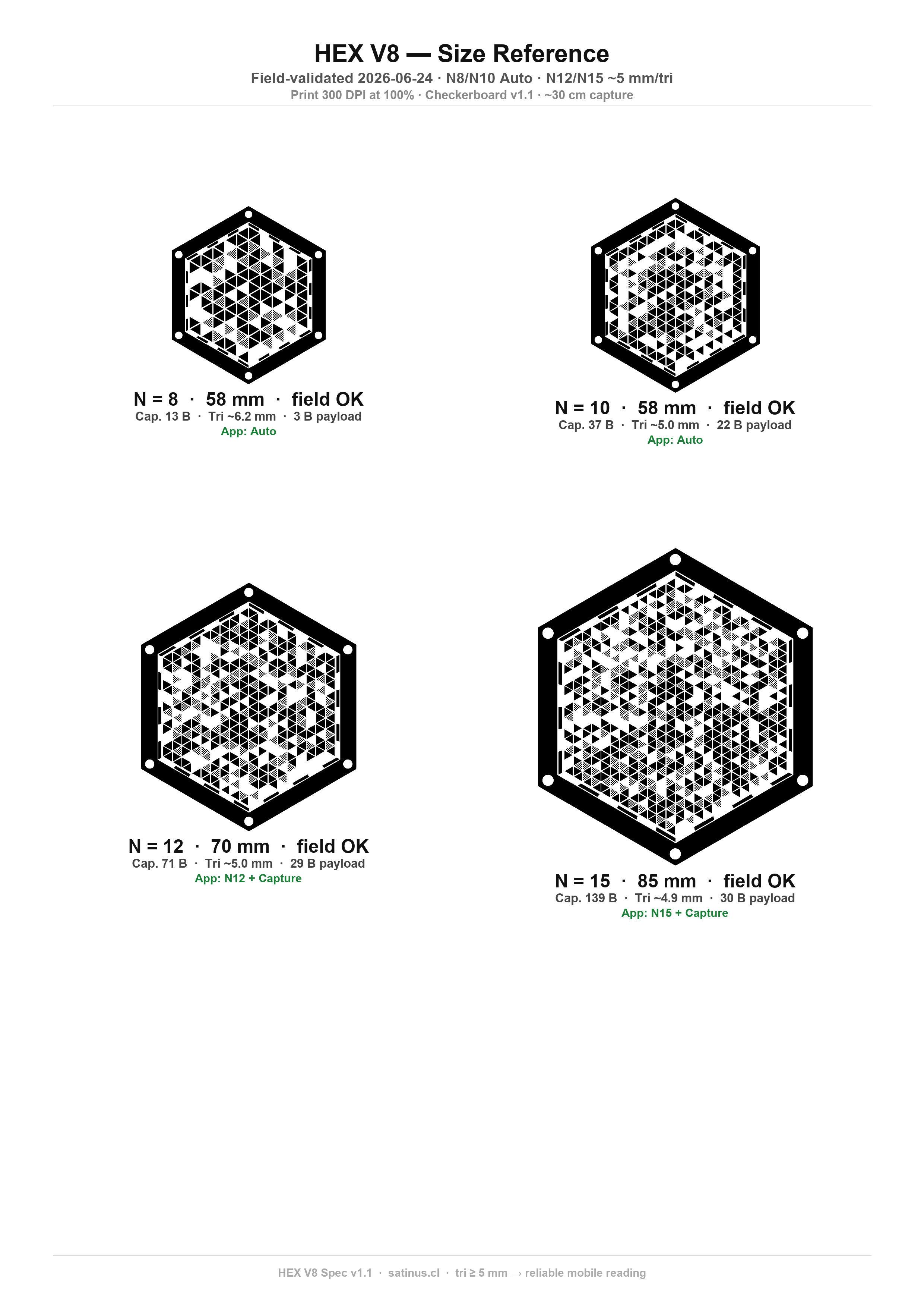
Figure 5. Field-validated sizes in millimeters; printed at 300 DPI, 100% scale. Cap. is geometric capacity (Table 2); Payload is the demo string on this sheet, not the RS-M maximum.
4.3 Useful capacity with RS (level M)
Geometric capacity is a bound on the space in rhombi; the maximum plaintext payload is smaller because the RS block occupies parity within that same space. For each N, the reference encoder searches for the largest admissible data_length with RS-M via binary search over the available space (June 2026); results are in the Max. data column of Table 2.
The Utilization column measures what fraction of the encodable trits in the mesh are used when the symbol is saturated (data + RS parity + packed header), not the simple data/geom ratio. As N increases, utilization rises (~83% at N8 → ~90% at N15) because the fixed overhead of 25 rhombi is diluted.
Geometric-to-useful relationship. Roughly, RS-M reserves ~20% of the block for parity; the difference between Geom. cap. and Max. data in Table 2 is small in bytes because the header is already deducted in the §4.1 formula and parity adjusts to the remaining space. Per-N layout detail in the technical report [18].
Table 2. Capacity by level N (RS-M)
| N | Geom. cap. (B) | Max. data (B) | Print (mm) | tri ≈ (mm) | Utilization (%) |
|---|---|---|---|---|---|
| 8 | 13 | 11 | 58 | 6.2 | 83 |
| 9 | 24 | 22 | 58 | 5.5 | 85 |
| 10 | 37 | 35 | 58 | 5.0 | 86 |
| 11 | 53 | 51 | 64 | 5.0 | 87 |
| 12 | 71 | 69 | 70 | 5.0 | 88 |
| 13 | 91 | 89 | 76 | 5.0 | 89 |
| 14 | 114 | 112 | 81 | 5.0 | 90 |
| 15 | 139 | 137 | 85 | 4.9 | 90 |
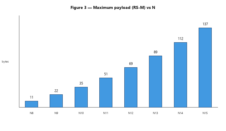
Figure 3. Growth of useful capacity with N (values from Table 2).
5. Mobile reader: from photo to payload
A higher-capacity symbol under the protocol of §4–§6 cannot be read by the phone's built-in QR scanner. A mobile decoding pipeline aligned with trits, hexagonal ring, and variable N is required. This section describes the architecture of the reader used in the field evaluation (release 0.4.7, July 2026)—the baseline of Sec.~5.6—complementary to the codec of §3.7.
5.1 Why a dedicated application is needed
Mobile decoding reuses standard components [8–12] — grayscale, homography, Reed–Solomon — but the QR assumption (binary module on a grid, rectangular finders, discrete version) does not transfer directly to HEX. The dedicated reader adds five capabilities that a QR pipeline lacks:
- Detection of the hexagonal visual ring and scale estimation before reading data.
- N resolution — the symbol can be N8, N10, N12, or N15 within the same session.
- Ternary classification per triangle, including the checkerboard texture of trit 1 (§3.6).
- Deinterleave by rings following the V8 write order (§3.5.3).
- Scene adaptation — paper, monitor with moiré, dense N15 — without draining the battery on a single costly sweep.
Without these pieces the payload cannot be recovered even with the correct decode engine: the bottleneck in the field is not the RS layer, but geometry + classification + retry policy.
5.2 Capture and region of interest
The UI fixes a framing box; upon capture, a region of interest (ROI) is cropped from the frame with empirical vertical bias correction (monitor: the symbol tends to sit slightly below the optical center unless compensated). Before decoding, scene metrics are computed — local contrast, variance, intensity spread — used by the router of §5.4.
Each attempt starts from a grayscale image. The first geometric step is to detect the visual ring: a radial sweep from the estimated center looking for the dark band of the hexagonal perimeter. From the ring, the refined center, orientation, and the ring ratio — the ratio between outer and inner radii — are obtained, which correlates with N (e.g., N10 ≈ 0.874, N15 ≈ 0.887). If the ratio is ambiguous, the reader keeps several N candidates rather than committing to a wrong one. When the quiet-zone timing pattern of §3.6 is present, the pipeline may score segment agreement as an optional auxiliary check of radial alignment; it does not replace ring detection or gate decode success.
5.3 Per-attempt geometric core
After detecting the ring, the pipeline runs the core shared with §3.7:
- Homography — rectifies the symbol's plane toward a canonical mesh, correcting perspective and rotation (anchors at sectors 0, 2, 4).
- Preprocessing — contrast, blur, and scaling variants according to stage S0/S1/S2 (§5.4).
- Trit sampling — per-triangle integral after rectification; trit 1 via checkerboard (§3.6).
- Rhombi and deinterleave — S2-octal symbols; inversion of the ring interleave (§3.5.3).
- RS + header — GF(256) with erasures at (1,1); V8 header validation (Table 1) and truncation to
data_length.
Latency sums capture (~1.4–2.0 s) and decode (tens of ms up to ~3.5 s at high N, §6.2). Retries multiply decode time, not capture time.
5.4 Profile router and stages S0 → S1 → S2
Before scaling up cost, the 0.4.7 reader classifies the scene (ProfileRouter). When in doubt on paper, the conservative route is the paper profile (faster).
| Profile | When chosen | Available stages |
|---|---|---|
| paper | Low probability of moiré; printed texture | S0 → S1 |
| screen | High variance, high contrast, moiré | S1 → S2 |
| dense | N15 in pill or in sessionNHint |
S1 → S2 |
| unknown | Scene not confidently classified | S0 → S1 → S2 |
Table 7. Behavior by profile and stage (summary)
| Profile | S0 | S1 | S2 |
|---|---|---|---|
| paper | Fast scan, few retries | More combos; N fixed if a hint exists | — |
| screen | — | Blurred + denseScanLite if session ≥ N12 (2 variants) | Moire scan |
| dense | — | Dense scan; abort after 2 hatch_fail at N15 | Moiré + dense |
| unknown | Fast | Standard combos | Moiré |
Stages S0–S2 are cost policies: more preprocessing combos and more retries per N candidate. On paper, most hits occur at S0; on a monitor at N15, S1 restricted to two variants avoided the 12–23 s sweeps of earlier releases. Many hatch_fail cases due to low framing do not exhaust S2: the operator reframes (centerDy ≈ −14 px on N15 hits, §6.2).
5.5 N resolution and session hint
In Auto mode, N resolution follows this order:
- Pill N — fixed N in UI → a single candidate.
sessionNHint— last successful N; chain 8 → 10 → 12 → 15; after N12, N15 is tried first.- Ring ratio — estimate from the ring; up to four candidates if ambiguous.
- Stage expansion — more candidates at S1/S2 if S0 failed.
With sessionNHint ≥ 12 on screen, the reader can fix N from the session and disable autoScan for N15 — validated at 4/4 on monitor (§6.3).
5.6 Evaluated baseline
The field campaign of July 2026 used the Android reader (release 0.4.7): ProfileRouter active, $N$ resolution before the sweep, persistent sessionNHint, S1 restricted on monitor N15, and experimental canonical warp disabled. The Sec.~6 metrics (centerDy, decodeMs, profile, stage, $N$ candidates, and failure reason) were recorded on that build during the protocol sessions.
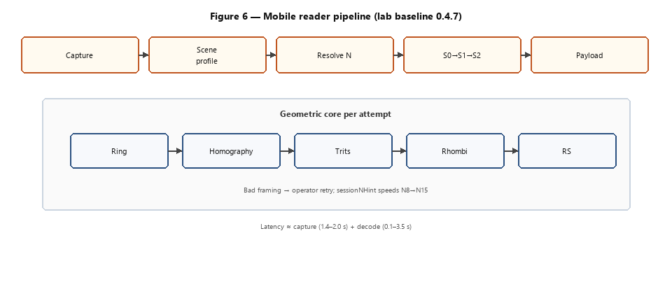
Figure 6. Decode pipeline of the evaluated baseline (ROI → profile → $N$ resolution → stages S0→S2 → geometric core → payload).
6. Experimental evaluation
This section answers the question of §2 regarding the artifact built in §3–§5. Experiments share a common protocol (§6.0); three axes are then reported: synthetic regression (§6.1), paper field tests (§6.2) and monitor field tests (§6.3), closing with the bounded comparison against QR (§6.4). Unless noted otherwise, mobile field metrics (centerDy, decodeMs, profile/stage) come from the 0.4.7 baseline of Sec.~5.6.
6.0 Evaluation protocol
Table 6. Fixed protocol parameters
| Parameter | Value | Notes |
|---|---|---|
| Reed–Solomon | Level M | ~20% parity (§3.5.4) |
| Printing | 300 DPI, 100% scale | No "fit to page" |
| Main substrate | White paper | Sheet in Fig. 5 |
| Capture distance | 25–35 cm | Extended arm, perpendicular view |
| Reference device | Redmi Note 9 Pro | Only documented hardware |
| Main camera | 64 MP, f/1.9, 26 mm eq., 1/1.72″ sensor, 0.8 µm pixel | Global variant [19]; other regions use 48 MP |
| Capture pipeline | Viewfinder ROI → JPEG → ~560 px width | Before decode (APK 0.4.7) |
| Decode buffer resolution | ~10–12 px/edge (N15, empirical) | Ring radius 126–164 px (§6.2) |
| Monitor channel | ThinkPad L14, integrated 14″ panel | WUXGA 1920×1200, IPS; viewer at 100% scale |
| Panel pixel pitch | $d_{\text{display}} \approx 0.157$ mm | $\sqrt{1920^2+1200^2}/14/25.4$; ThinkPad L14 WUXGA [20] |
| px/edge on screen (N15) | $p_{\text{tri,display}} \approx 31$ | $\text{tri_mm}/d_{\text{display}}$; before capture |
| Moiré sensitivity | $f_{\text{display}} \approx 6.4$/mm vs $f_{\text{cam}} \approx 2.2$/mm | $f=1/d$; see §6.3 |
| Reader | APK 0.4.7 | July 2026; baseline for this paper |
| Session mode | Auto N8→N15 | Sequential after each success |
| Legibility criterion | tri_mm ≳ 5 mm | Sizes in Table 2 / Fig. 5 |
| Success metric (paper) | Sequential 4/4 OK | N8, N10, N12, N15 in one session |
| Latency metric | decodeMs |
Excludes UI capture time |
Field procedure (paper). (1) Print the reference sheet (Fig. 5). (2) Install the APK 0.4.7 used for this study. (3) Open Auto mode; after each correct reading, advance to the next N without restarting the session. (4) Frame the active symbol within the box; at N15, center the code slightly above the optical center (centerDy ≈ −14 px on hits).
Acceptable vs. blocking failure criteria. A miss due to hatch_fail or an invalid header with a positive centerDy is classified as a framing error, not a codec regression. An RS failure with a well-centered symbol and correct profile would be blocking; none was observed in the July 2026 sessions.
Angular resolution (paraxial). Discrimination of the checkerboard trit (Sec.~3.6) and the $\mathrm{tri_mm}\approx 5\,\mathrm{mm}$ threshold (Sec.~4.2) depend on capture distance $D$ and on optical angular resolution—effective focal length $f$ and sensor pixel pitch $p$ (Table 6). Under a pinhole model in the paraxial regime (lens distortion negligible near the optical axis), the triangle edge projected onto the sensor occupies
$$p_{\text{tri,sensor}} \approx \frac{\text{tri_mm}}{D} \cdot \frac{f}{p}$$
(with lengths in mm). Barrel/pincushion terms are omitted: inside the viewfinder ROI the radial offset is small relative to $D$, and typical mobile wide-angle polynomials are second-order when $|r|\lesssim 0.3\,D$.
From full frame to decode buffer. With $\mathrm{tri_mm}\approx 4.9\,\mathrm{mm}$, $D\approx 30\,\mathrm{cm}$, $f\approx 5.6\,\mathrm{mm}$ (26\,mm equivalent on a $1/1.72''$ sensor) and $p\approx 1.6\,\mu\mathrm{m}$ (usual 4:1 binning for this sensor class), the full-frame order of magnitude is $\sim$50\,px/edge before crop. The pipeline crops the ROI and resizes to $\sim$560\,px width; N15 hits report ring radii of 126--164\,px, i.e. $\sim$10--12\,px/edge in the decode buffer—a narrow margin for trit~1 texture, aligned with the operational threshold. Peripheral degradation at N15 is treated as a field limit (Sec.~7.1), not as a correction inside this estimate. Devices with different $f/p$ or dynamic range may fall below that margin without any change to the printed symbol, motivating the multi-device matrix (Sec.~7.1, Sec.~8.4).
6.1 Synthetic corpus
The laboratory regression corpus consists of 15 PNG images generated from a base symbol (N=8, payload Hola HEX) with controlled degradations. Table 3a summarizes variants and quantitative success rates.
Table 3a. Synthetic N8 corpus — success rates by family (Python and TypeScript, June 2026)
| Family | Variants (n) | Degradation | Python success | TypeScript success |
|---|---|---|---|---|
| baseline | 1 | pristine image | 1/1 | 1/1 |
| jpeg | 3 | quality 92 / 80 / 70 | 3/3 | 3/3 |
| blur | 2 | light / medium gaussian | 2/2 | 2/2 |
| contrast | 2 | 0.65× / 1.35× | 2/2 | 2/2 |
| shift | 3 | ±24 px, +40 px vertical | 3/3 | 3/3 |
| perspective | 2 | 8° / 12° rotation | 2/2 | 2/2 |
| resize | 2 | 480 / 560 px | 2/2 | 2/2 |
| Total | 15 | — | 15/15 (100%) | 15/15 (100%) |
Regression command: npm run benchmark:matrix (June 2026). Python engine p95 latency ≈ 898 ms per image on laboratory hardware. This corpus validates the codec before printing-specific noise and the capture UI; it does not substitute for the field protocol of §6.2–6.3.
6.2 Paper field tests
Sessions from July 2026 with APK 0.4.7 on the sheet from Fig. 5.
Table 3. Paper results
| N | mm | tri ≈ (mm) | Result | Notes |
|---|---|---|---|---|
| 8–15 (sequential) | scaled sheet | ≥ 4.9 | 4/4 OK | July 2026 session |
| 8 | 58 | 6.2 | OK | historical 0.3.0 |
| 10 | 58 | 5.0 | OK | historical 0.3.0 |
| 12 | 70 | 5.0 | OK | historical 0.3.0 |
| 15 | 85 | 4.9 | OK | historical 0.3.0 |
Telemetry from the confirmatory session (2026-07-04). Four sequential correct readings N8→N15; five additional misses, all when attempting N15 with the symbol below the box's center (centerDy +11…+26 px): three garbage_header, one crc_fail, and one hatch_fail. Successful N15: decodeMs 2955 ms, centerDy −14 px, stage S0, profile paper. Range of decodeMs on hits: 116–3524 ms (marginal p95 3524 ms at N12, above the 3 s regression threshold but with no functional failure).
Interpretation. The V8 format is stable on paper; the operational bottleneck is framing at N15, consistent with the greater visual density and active area of the symbol. Figure 9 (left column) documents successful N8→N15 readings under the printed-sheet conditions.
6.3 Monitor field tests (secondary)
The monitor channel is secondary: it validates the reader's screen profile (Sec.~5.4) under moiré and reflections, but paper remains the primary demonstration substrate. Figure 9 (right column) shows successful monitor readings for the same $N$ levels as on paper.
Moiré (why it is less reproducible than paper). Digital moiré is a beat between the panel spatial frequency $f_{\text{display}}=1/d_{\text{display}}$ and the pipeline sampling density $f_{\text{cam}}=p_{\text{tri,decode}}/\mathrm{tri_mm}$ after ROI resize (Sec.~6.0). On the documented ThinkPad L14 WUXGA panel [20], $d_{\text{display}}\approx 0.157\,\mathrm{mm}$ so $f_{\text{display}}\approx 6.4\,\mathrm{cycles/mm}$. Displayed at the same physical millimeters as Fig. 5 (100\% zoom), N15 yields $p_{\text{tri,display}}\approx 31\,\mathrm{px/edge}$ on the panel and, after the pipeline, $p_{\text{tri,decode}}\approx 11\,\mathrm{px/edge}$ ($f_{\text{cam}}\approx 2.2\,\mathrm{cycles/mm}$). When mesh or checkerboard harmonics approach the Nyquist limit $f_{\text{cam}}/2$, the beat aliases trit~1 texture and elevates hatch_fail rates—distinct from RS failure. Panels with a different $d_{\text{display}}$ change that coupling; hence monitor results are not interchangeable with paper.
Golden sessions 2026-07-03 and 2026-07-04 used this L14 as the sole test screen. N8/N10 on monitor required $\sim$6--7\,s of decoding (screen, S1 with moiré) before sessionNHint locked; successful N12/N15 then fell to 136--1333\,ms with fine framing. Session 2026-07-03: 4/4 OK, N15 in 1333\,ms (blurred, two variants, S1 only). Confirmation 2026-07-04: 4/4 OK after eight framing misses; N15 in 458\,ms at centerDy$\approx -15\,\mathrm{px}$. Misses again track positive vertical displacement (+1$\ldots$+16\,px). With sessionNHint\geq 12, S1 is restricted to two variants, avoiding the 12--23\,s sweeps of earlier releases.
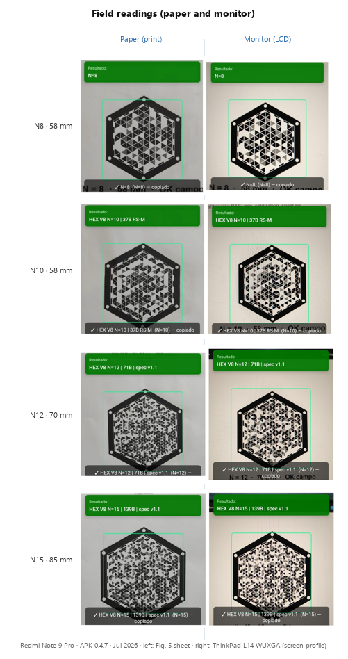
Figure 9. Reader-app captures (APK 0.4.7, Redmi Note 9 Pro, July 2026): by row, paper (left, sheet from Fig. 5) and monitor (right, ThinkPad L14 WUXGA, screen profile) for N8, N10, N12, and N15. Each panel shows a successful decode under the protocol of Sec.~6.0. On-screen banners report geometric capacity bytes (Table 2); useful RS-M maxima are 11/35/69/137 B.
6.4 Bounded comparison with QR
Narrative this section rejects. HEX V8 is not framed here as “the hexagonal evolution of QR,” as a drop-in successor, or as a format that is simply “3.7× denser.” The ratio $137/37$ that appears when N15 is set beside the ~25 mm reference QR is a protocol payload ratio (same $\mathrm{tri_mm}$ band / declared RS-M), not a same-size density contest. The decisive axis is useful bytes at comparable mobile legibility; full-footprint bits/mm² and ecosystem universality are deliberately secondary (§7.3, Table 5b).
Table 4 contrasts the channel model of the typical binary symbologies of §1 with HEX V8 (Figure 8d). Table 5 summarizes reference payloads under the field protocol (Figure 8). Table 5b adds printed hexagonal area and useful density in bits/mm² (Figure 8c).
Table 4. Qualitative model: typical ISO symbologies vs. HEX V8
| Aspect | QR / Data Matrix / Aztec | HEX V8 |
|---|---|---|
| Alphabet per element | Binary (module) | Ternary (trit per triangle) |
| Topology | Grid | Triangular hexagonal mesh |
| Encoding unit | Module | S2-octal rhombus (3 bits) |
| Synchronization | Finders, bullseye, perimeter | Hexagonal visual ring |
| Correction | RS GF(256) | RS GF(256) + native erasures (1,1) |
| Density scale | Version / module size | Parameter $N$ (radial mesh divisions) + size in mm |
| Reader | Universal (smartphone) | Dedicated application |
Table 5. Reference payload (field protocol, sizes from the size-reference sheet)
| Symbol | Printed size | Useful payload (RS-M) | tri ≈ (mm) |
|---|---|---|---|
| QR demo | ~25 mm | ~37 B | — |
| HEX N10 | 58 mm | 35 B | 5.0 |
| HEX N15 | 85 mm | 137 B | 4.9 |
Table 5b. Useful density and area (HEX V8 RS-M vs. reference QR §6.4)
Area of the hexagon with flat-to-flat width (W): (A = \frac{\sqrt{3}}{2} W^2). Density: (8 \times \text{payload (B)} / A). The reference QR uses a square box (W\times W) as an area bound (it is not a hexagon).
| Symbol | (W) (mm) | Min. element | (A) (mm²) | Payload (B) | bits/mm² |
|---|---|---|---|---|---|
| HEX N8 | 58 | tri ≈ 6.2 | ≈ 2913 | 11 | ≈ 0.030 |
| HEX N10 | 58 | tri ≈ 5.0 | ≈ 2913 | 35 | ≈ 0.096 |
| HEX N12 | 70 | tri ≈ 5.0 | ≈ 4243 | 69 | ≈ 0.130 |
| HEX N15 | 85 | tri ≈ 4.9 | ≈ 6257 | 137 | ≈ 0.175 |
| QR ref. | ~25 | fine module | ≈ 625 (box) | ~37 | ≈ 0.47 |
How not to read Tables 5–5b. A ratio such as $137/37\approx 3.7$ is a payload ratio under the declared protocol, not evidence that HEX N15 occupies the same millimeters as the reference QR, nor that HEX wins on bits/mm² of full footprint (Table 5b shows the opposite for full-hexagon area). There is no “QR N15 equivalent” in this manuscript: the QR point is a ~25 mm field demo, while HEX N15 is an 85 mm symbol at $\mathrm{tri_mm}\approx 5\,\mathrm{mm}$.
The fair comparison is not simply "more bytes in fewer millimeters," but more bytes while maintaining mobile legibility. The operational indicator adopted is the printed triangle edge (tri_mm ≈ 5 mm, §4.2). Under that constraint, a reference QR printed at ~25 mm under the same capture-distance band (§6.0) carries ~37 B of useful payload in the field comparison sheets (a bounded demo point, not a claim over all QR versions or ECC levels). HEX N10 at tri ≈ 5 mm (~58 mm flat-to-flat width) reaches 35 B of useful data (RS-M) — the same order of magnitude —; HEX N15 at tri ≈ 5 mm (~87 mm theoretical; 85 mm in the field) reaches 137 B (Figure 8b). Table 5 lists the sizes validated in the field (Fig. 5): at N15 the protocol uses 85 mm (tri ≈ 4.9 mm), slightly below the nominal threshold but within the observed margin (§6.2). HEX does not reduce the footprint in mm relative to a small QR: it trades a larger printed hexagon for more payload as $N$ scales, holding triangle-edge readability near the declared threshold. Phrases such as “superior capacity” or “higher density” are therefore unsafe without that trade-off stated in the same breath.
Reading Table 5b. Two density readings must be kept distinct. (i) Full-footprint density uses the printed hexagonal area $A(W)$ and yields ≈0.175 bits/mm² for HEX N15 at 85 mm — lower than the reference QR at ~25 mm (≈0.47 bits/mm²), because the HEX footprint includes ring and quiet zone. (ii) Trit-kernel density restricts the area to (W_K=W\cdot K/N) (encodable mesh only) and raises N15 to about ≈0.27 bits/mm²; that figure is an auxiliary alphabet metric, not a claim for label marketing. Under the declared protocol the decisive comparison is therefore not “more bits per mm² at any scale,” but more useful bytes at comparable legibility (tri_mm ≈ 5 mm), with HEX full-footprint density still growing with N at nearly fixed tri (≈0.030 → ≈0.175 bits/mm² from N8 to N15; Figure 3, Figure 8b). Data Matrix [2] shares the per-module binary alphabet of Table 4; a specific ISO data point is not tabulated here under the same field protocol, so as not to mix nominal version capacities with the already-bounded QR reference of §6.4.
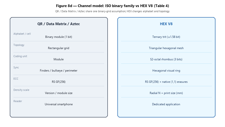
Figure 8d. Qualitative channel-model contrast (Table 4): QR / Data Matrix / Aztec share a binary grid alphabet; HEX V8 changes alphabet, mesh, and reader.
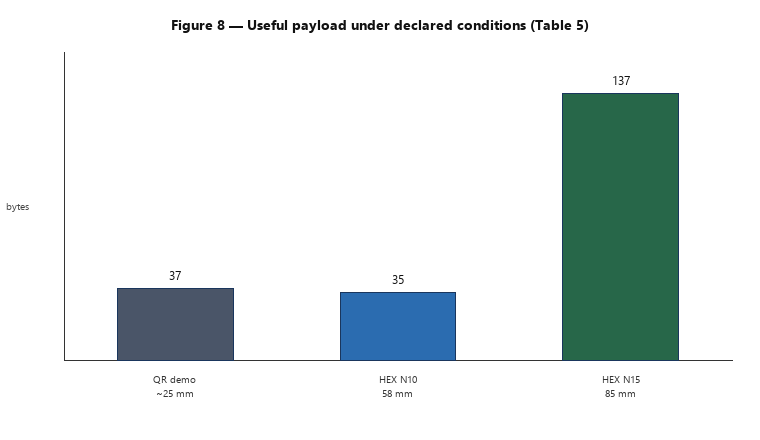
Figure 8. Useful payload (RS-M) under the field protocol (Table 5): ~25 mm reference QR versus HEX N10 and N15.
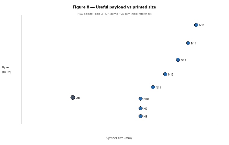
Figure 8a. Relationship between useful bytes (RS-M) and symbol size (Table 2); reference QR point included.
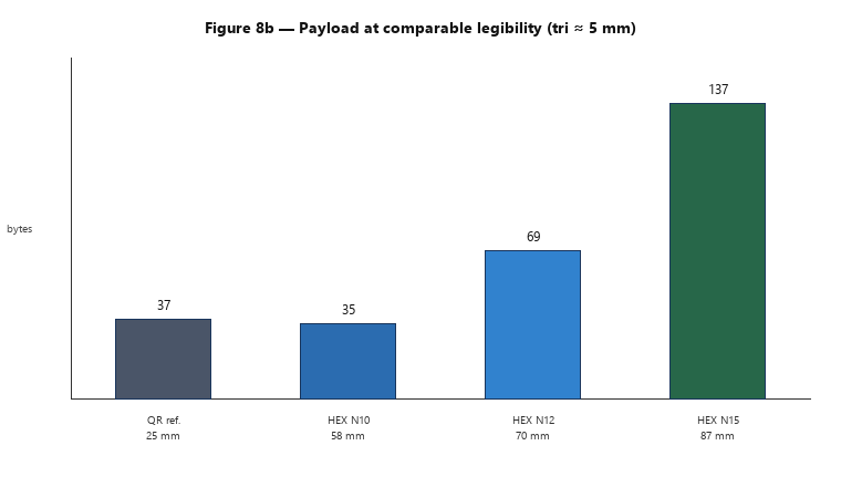
Figure 8b. Comparison at comparable legibility (same printed triangle edge $\approx 5\,\mathrm{mm}$)---not at equal overall width.
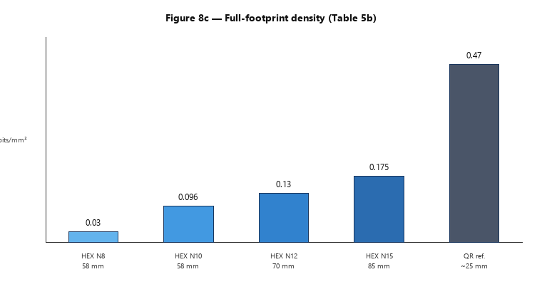
Figure 8c. Full-footprint useful density (bits/mm²; Table 5b). The ~25 mm reference QR is denser by area; HEX wins on bytes at matched tri as $N$ scales.
7. Limitations
The evidence in §6 supports the question of §2 under explicit rules; outside that framework the format and reader should not be extrapolated without new measurements.
7.1 Experimental scope
The field evaluation documents a single device (Redmi Note 9 Pro, Table 6) and one build of the reader (APK 0.4.7, Sec.~5.6). There is no hardware matrix across OEMs, no second operating system, and no controlled lighting sweep. The synthetic corpus's 15/15 score (§6.1) validates the codec against image degradations, but does not substitute for printing variability, framing, or mobile UI latency (§6.2–6.3). Field results are therefore a proof of concept on that baseline: sensors with lower dynamic range, different ISP pipelines, or stronger wide-angle distortion can shift ring detection, hatch success, and decodeMs. Generalization requires the multi-device matrix prioritized in §8.4.
Paraxial model versus peripheral optics. Two layers must not be conflated. (1) Paraxial / central ROI. The projection model of §6.0 (pinhole, small radial offset) relates triangle edge, distance D, focal length f, and pixel pitch p inside the viewfinder box where the symbol is intended to sit. It explains the order of ~10–12 px/edge in the decode buffer and supports transfer estimates of $p_{\text{tri,sensor}}$ across devices. (2) Peripheral / off-axis degradation. When the 85 mm N15 ring drifts toward the lens periphery, radial aberration and field curvature rise; that regime is outside the paraxial sweet spot and is treated as a hardware/optics field limit, not as evidence of codec fragility.
Angular framing tolerance. The centerDy telemetry (vertical displacement of the detected ring center relative to the decode-buffer center, in px) maps into the same angular units. With effective sensor height $h_{\text{sensor}}$ (≈ 7.2 mm on 1/1.72″), focal length f, capture distance D, and buffer height $H_{\text{decode}}$ (≈ 560 px, Table 6),
$$\delta\theta_y \approx \frac{\text{centerDy}}{H_{\text{decode}}} \cdot 2\arctan\frac{h_{\text{sensor}}}{2f}$$
(equivalently, $\delta y \approx D \tan\delta\theta_y$ in the symbol plane). With f ≈ 5.6 mm, D ≈ 30 cm, and the Redmi Note 9 Pro baseline, each centerDy pixel is ≈ 0.7 mm and ≈ 0.12° in the scene. In the confirmatory session of §6.2, N15 hits concentrate near −14 px (≈ −1.7°, symbol slightly above the optical center); the five N15 misses lie at +11…+26 px (≈ +1.3°…+3.1°, symbol below the box). The empirical elevation window is therefore on the order of ±2° — consistent with layer (2) above (peripheral optics), and not with Reed–Solomon or S2-octal failure under a well-centered symbol.
The decodeMs metric of §6.2–6.3 is not generalizable without a multi-screen/multi-device matrix (§8.4). The paraxial model of §6.0 still allows estimating $p_{\text{tri,sensor}}$ on other devices before measuring field latency.
7.2 Scope of the format and of the operation
Levels N8–N15 are validated on mobile under the protocol of §6.0. The Auto chain 8 → 10 → 12 → 15 omits the intermediate odd N values (9, 11, 13) despite being encodable (Table 2): this is not a codec limitation, but a decision of field protocol and angular geometry.
Geometry and phase incompatibility. The honeycomb has six sectors with $K^2$ triangles each ($K=N-3$, §4.1). The reader estimates N by rotating an angular sampling grid with step $\Delta\theta = 360°/N$ over the barycentric mesh, while the format's timing anchors — visual ring and sectors 0, 2, 4 (§3.4) — are fixed at phases $0°$, $120°$, and $240°$. An N is harmonic when $\Delta\theta$ evenly distributes those phases; equivalently, $360° \bmod N = 0$. N11 and N13 violate that phase coherence: the rotational sweep does not uniquely align the estimation grid with the symbol's anchors, which increases ambiguity when resolving N — they are classified as dissonant in the design heuristic [18], not as a codec failure. N9 is harmonic, but adds a density step nearly iso-capable with N10 under the same tri_mm (Table 2) with no operational benefit; including it would fragment the candidate space of the N sweep and of the ProfileRouter (§5.4–5.5). The +2 progression up to N12 keeps capacity steps evenly spaced with symmetric sectors; N15 closes the chain as the validated dense extreme (odd but harmonic: $\Delta\theta = 24°$).
With N ≥ 18 and a triangle edge below ~5 mm, reading ceases to be reliable in the tests performed.
The operational bottleneck at high N is framing, not the codec (a phenomenon directly correlated with the peripheral optical aberration anticipated in §7.1): on paper, the misses of the confirmatory session (§6.2) are explained by positive centerDy when N15 sits below the box's center. The monitor channel (ThinkPad L14, $d_{\text{display}} \approx 0.157$ mm, §6.3) is secondary and less stable than paper due to moiré — sensitive to the $f_{\text{display}} \times f_{\text{cam}}$ coupling — and reflections, though it confirms the reader's screen profile.
HEX V8 provides no intrinsic confidentiality: the payload remains in the clear within the symbol; error correction protects integrity against physical damage, it does not substitute for encryption or application authentication. Alternative packings on the same mesh (e.g. grouping three rhombi per hexagon) were explored outside the canonical codec and did not improve capacity or byte alignment (§3.4).
7.3 Comparison, ecosystem, and document status
The comparison with QR (§6.4, Tables 4–5) is bounded to the declared protocol — RS-M, tri_mm ≈ 5 mm, a reference QR at ~25 mm — and does not aim to cover the full ISO ecosystem nor all QR correction levels.
HEX requires a dedicated reader and explicit printing rules; it does not compete in reading universality with built-in QR cameras. This manuscript is a preprint without peer review. Extended reproducibility — detailed specification, tables, field telemetry, and regression procedures — is documented in the technical report [18].
8. Conclusions and deliverables
8.1 Answer to the question in §2
The question in §2 admits an affirmative and bounded answer. Under the protocol conditions (§6.0, Table 6) — controlled monochrome printing, tri_mm ≳ 5 mm as the legibility criterion, a dedicated reader with profiles and N resolution (§5) — the evaluated HEX V8 artifact carries more useful bytes than the declared QR references at comparable legibility: up to 137 B at N15 / ≈85 mm with RS-M (Table 2, Figure 8b) versus ~37 B for a reference QR at ~25 mm. The affirmative answer is not “HEX replaces QR” and not “137 B fit in a 25–58 mm label”; it is “more useful bytes when triangle-edge legibility is held near 5 mm.” No validity is claimed outside that framework (§7).
The evidence is complementary, not interchangeable:
- Codec — synthetic regression 15/15 (§6.1): a necessary test of the logical engine against JPEG, blur, shift, and perspective; it does not substitute for printing or the capture UI.
- Field — sequential 4/4 OK N8→N15 on paper with APK 0.4.7 (§6.2, Figure 9), on one documented device. The five misses of the N15 confirmatory session carry centerDy +11…+26 px (≈ +1.3°…+3.1°, outside the paraxial sweet spot of §7.1); the corresponding hit uses centerDy −14 px (≈ −1.7°) — a pattern of peripheral framing, not RS failure. At high $N$ the operational bottleneck is framing/optics, not Reed–Solomon.
- Comparison — operational criterion tri_mm ≈ 5 mm (§6.4), not nominal density in mm² and not same-footprint packing; at equal legibility, N15 surpasses the reference QR in payload, not in minimum printed footprint.
What we do not claim (already excluded in §2 and detailed in §7): a substitute for QR in ecosystem or ISO standard terms; an evolutionary “next QR”; intrinsic confidentiality; universal reading without a dedicated app; generalization to other hardware without new measurement; a same-size “3.7× denser” label claim. HEX trades footprint for payload as $N$ scales, under a dedicated reader and with framing sensitivity at N15 — consistent with the design arc of §3 (the binary edge of §3.2 did not reach that payload band; V8 does, under the rules above).
8.2 Contributions
The following summarizes what is substantiated in §3–§6, aligned with the non-scope of §2 and the limitations of §7:
- Convergent HEX V8 specification with documented design evolution (§3).
- Closed geometric capacity model and empirical N8–N15 table with RS-M (§4, Table 2).
- Channel co-design: ring interleave, native (1,1) erasures, 8-byte V8 header (Table 1), and deterministic padding (§3.5).
- Visual layer v1.1 (checkerboard) for monochrome printing at 300 DPI (§3.6).
- Mobile reader with
ProfileRouter, stages S0–S2, and $N$ resolution (§5, Table 7), evaluated under the declared protocol with the 0.4.7 build (§5.6, §6.0).
8.3 Deliverables
Reproducible evidence and materials associated with the study (not commercialization of the format):
| Deliverable | Description |
|---|---|
| HEX V8 Format | Convergent specification (§3.7); extended detail in [18] |
| Capacity tables | Table 2; per-N RS-M PDF sheets |
| Reference sheets | Sizes in mm and tri per N; maximum capacity (Fig. 5) |
| 15/15 Corpus | Synthetic regression: shift, perspective, JPEG, blur, contrast |
| Android Reader 0.4.7 | Field baseline for Sec.~6 |
| Satinus Technical Report [18] | Specification, protocol, reader architecture, and field record |
| This preprint | Public synthesis of the design, data, limits (§7), and materials (§9) |
8.4 Future work
Priorities, ordered by evidential impact:
- Multi-device / multi-ISP matrix — repeat the Sec.~6.0 paper protocol on at least two additional phones (distinct sensor formats and wide-angle distortion). Report per-device centerDy windows, N15 hit rate, and
decodeMsdistributions so the Redmi Note 9 Pro baseline is no longer the sole field anchor. - Multi-screen validation — panels with $d_{\text{display}}$ different from the ThinkPad L14 of Sec.~6.3, separating moiré coupling from codec behavior.
- Protocol extensions — odd $N$ and $N\geq 18$ at measured $\mathrm{tri_mm}$; formal BER comparison against QR under identical print/capture rules.
- Operations — public field-capture dataset with telemetry; N15 framing aids (guide or adaptive ROI); public specification 1.0.
Beyond measurement, HEX V8 is positioned as a specialized channel with a dedicated reader (Sec.~5.1, Sec.~7.3), not as an OS-camera substitute for QR. Prospective industrial uses—dense part labeling, plant-floor traceability, technical packaging—accept that trade-off when payload at $\mathrm{tri_mm}\approx 5\,\mathrm{mm}$ matters more than minimum marketing footprint; they are not validated in Sec.~6 and motivate the collaboration path in Sec.~9. A browser encoder/decoder (Sec.~9) supports didactic roundtrips and capacity exploration; it does not replace the Android field baseline.
9. Availability of documentation and materials
Extended technical documentation is published as a Satinus E.I.R.L. technical report [18]:
https://satinus.net/docs/informes/hex-v8-informe-tecnico.html.
Online materials (documentation hub):
- Spanish HTML preprint
- Technical report [18]
- Size reference sheet (PDF) and maximum RS-M capacity (PDF)
- HEX encoder/decoder (browser) — TypeScript roundtrip tool (15/15 vs Python on Sec.~6.1); didactic only, not a substitute for APK 0.4.7
Field reader. The Android reader lineage used in Sec.~6 is released via GitHub (hex-scanner): signed APK, release notes, and in-app update channel. It is not listed on app stores during the preprint phase.
Reuse and contact. Deliverables listed in Sec.~8.3 and the public materials above are free for didactic use, format evaluation, and partial reproduction of the Sec.~6.0 protocol. The reference algorithmic core and commercial exploitation remain with Satinus E.I.R.L. (Chilean IP Law N°~17.336). Collaboration, licensing, and support for further format/reader development are available by agreement.
Contact: jorgefigueroacifuentes@gmail.com, satinuseirl@gmail.com (Satinus E.I.R.L., Chile).
References
- ISO/IEC 18004:2015 — QR Code. iso.org/standard/62021
- ISO/IEC 16022:2006 — Data Matrix.
- ISO/IEC 24778:2024 — Aztec Code. iso.org/standard/82441
- ISO/IEC 15438:2015 — PDF417. iso.org/standard/65502
- I. S. Reed and G. Solomon, J. SIAM, 8(2):300–304, 1960. DOI: 10.1137/0108018
- ISO/IEC 15415:2011 — Print quality for 2D symbols.
- DENSO WAVE — QR development history. denso-wave.com
- E. Ohbuchi et al., Proc. Cyberworlds, IEEE, 2004. DOI: 10.1109/CYBER.2004.144
- J.-A. Lin and C.-S. Fuh, Math. Probl. Eng., 2013. DOI: 10.1155/2013/848276
- L. F. F. Belussi and N. S. T. Hirata, Proc. SIBGRAPI, IEEE, 2011.
- K. Zuiderveld, Graphics Gems IV, 1994.
- G. Bradski and A. Kaehler, Learning OpenCV, O'Reilly, 2008.
- D. Parikh and G. Jancke, IEEE WACV, 2008.
- O. I. Bulan et al., Color Imaging Conf., 2011.
- ISO/IEC 16023:2000 — MaxiCode.
- AIM, Inc., DotCode Symbology Specification 4.0, 2019.
- H. Kato et al., IEEE Pervasive Computing, 6(4):76–85, 2007.
- Satinus E.I.R.L., HEX V8 — Technical specification, capacity tables and evaluation protocol, technical report (online), 2026. satinus.net/docs/informes/hex-v8-informe-tecnico.html
- Xiaomi Redmi Note 9 Pro — camera specifications (global variant). gsmarena.com/xiaomi_redmi_note_9_pro-10217
- Lenovo ThinkPad L14 — panel specifications (14″ WUXGA 1920×1200 IPS). psref.lenovo.com — ThinkPad L14
Appendix A — Term index
Quick reference. Full definitions appear at the first mention in the body text.
| Term | § first mention |
|---|---|
| data payload | §1 |
| binary module / grid | §1 |
| Reed–Solomon | §1, §3.5 |
| HEX (name) | §3 |
| trit | §3.3 |
| triangular hexagonal mesh | §3.3 |
| rhombus / S2-octal | §3.4 |
| N | §3.4 |
| V8 header | §3.5.2 |
| ring interleave | §3.5.3 |
| native erasure / (1,1) | §3.5.1 |
| deterministic padding | §3.5.5 |
| spec v1.1 / checkerboard | §3.6 |
| quiet zone / QZ timing (optional) | §3.6 |
| visual ring / ring ratio | §5.2 |
| ProfileRouter / capture profile | §5.4 |
| stages S0/S1/S2 | §5.4 |
| sessionNHint / N resolution | §5.5 |
| tri_mm / code_mm | §4.2 |
| hatch_fail / centerDy | §6.2 |
| evaluation protocol | §6.0 |
Appendix B — Index of tables and figures
Floats are numbered automatically in the PDF; body text uses cross-references. This index lists titles by narrative section.
| Title | Section |
|---|---|
| V8 header layout (8 bytes) | Sec.~3.5.2 |
| Capacity by level $N$ (RS-M) | Sec.~4.3 |
| Synthetic N8 corpus (success by family) | Sec.~6.1 |
| Paper field results | Sec.~6.2 |
| Qualitative model vs. ISO symbologies | Sec.~6.4 |
| Reference payload (field protocol) | Sec.~6.4 |
| Useful density and area (HEX vs. ref. QR) | Sec.~6.4 |
| Evaluation protocol parameters | Sec.~6.0 |
| Reader behavior by profile and stage | Sec.~5.4 |
| Design evolution | Sec.~3 |
| S2-octal alphabet (8 data + erasure) | Sec.~3.4 |
| Trit alphabet (atlas) | Sec.~3.6 |
| Checkerboard detail (trit 1, printed) | Sec.~3.6 |
| Bidirectional encode / decode flow | Sec.~3.7 |
| Annotated HEX $N{=}10$ symbol | Sec.~3.7 |
| Size reference sheet | Sec.~4.2 |
| Maximum payload (RS-M) vs $N$ | Sec.~4.3 |
| Mobile reader pipeline 0.4.7 | Sec.~5.6 |
| Payload vs printed size | Sec.~6.4 |
| Payload at $\mathrm{tri}\approx 5\,\mathrm{mm}$ | Sec.~6.4 |
| Paper and monitor field readings (N8--N15) | Sec.~6.3 |